On a boat, there are numerous ways for water to find its way in. Whether it’s rainwater, water from the pipes, a leaking propeller shaft, or spray during sailing: some rainwater often ends up in the bilge.
The bilge is the lowest part of a ship, where the two sides meet to form the keel. This is where water, oil, mud, and other rubbish can collect. You ideally want to keep this area clean and dry.
The solution for dampness and dirt in the bilge is a reliable bilge pump. At AB Marine Service you’ll find automatic bilge pumps that do the work themselves as soon as there’s water in the bilge. This way you don’t have to keep an eye on whether pumping is needed.
What a bilge pump does
The bilge pump has a number of functions. Without a bilge pump, your vessel could become heavier, unstable, or sustain damage. In the worst-case scenario, it could even sink your boat. Naturally, we’d rather avoid that.
Pumping water out of the bilge
The main job of the bilge pump is to pump out water that’s ended up in the bilge. This could be rainwater, or water that’s got in through a leak or spray. That’s why a bilge pump is always fitted at the lowest point of the bilge, because water collects there and can be pumped out efficiently.
Protection against oil and debris
The bilge can accumulate much more than just water. Think of small residues of oil, dirt, or even diesel. A strong pump prevents this muck from building up and potentially causing damage. It’s important, however, to regularly check the pump and hoses for blockages or debris.
How does a bilge pump work?
There’s a range of bilge pumps on the market. The key difference is between manual and automatic models.
Manual bilge pump with switch
With a manual bilge pump, you operate the pump yourself using a switch or a control panel. This allows you to decide when to turn the pump on and off. You’ll need to be the one monitoring whether pumping is actually required, though.
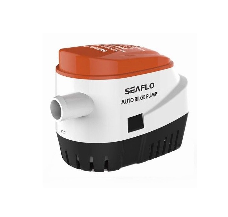
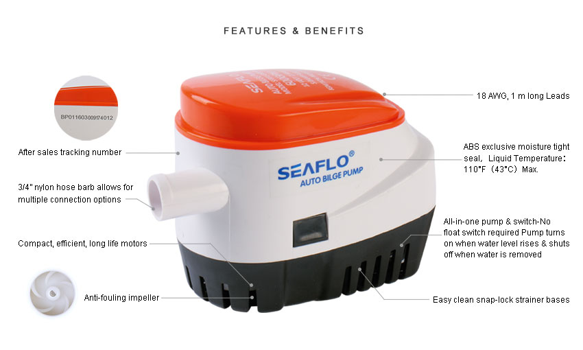
Automatic bilge pump with built-in float
When a pump has automatic operation, it has a float switch or built-in float. As the water level rises, the float moves up, and the pump switches on automatically. It then pumps out the bilge water until the level drops below a certain point again.
What do you need to connect a bilge pump?
Connecting a bilge pump is a job most DIYers can manage quite well. The aim is a safe and watertight connection for the pump, with no risk of a short circuit. Make sure you have the following bits and bobs to hand:
- A suitable bilge pump
- A switch or control panel
- Wiring tools
- Sturdy cables
- A fuse
- Hose clamps
- A cooling water hose
- A battery connection
Connecting the bilge pump: step-by-step explanation
Right then, time to get that bilge pump wired up. We’ll walk you through it in five straightforward steps. If you’re missing a bit or fancy asking a question, just give our experts a shout.
Step 1: Choose the right location
Find the location of the bilge pump. You’ll want the pump in the lowest part of the hull, as that’s where all the water will drain. Ensure the pump is securely mounted and easy to install. Allow ample space for the hose and wiring.
Step 2: Connect the hose
Attach the drain hose to the pump. Use one or two hose clamps to create a secure and watertight seal. Route the hose upwards, ensuring the outlet always remains above the waterline. This prevents water from flowing back down the hose.
Step 3: Wiring and fuse
Connect the pump to the boat’s power supply. Always fit a separate fuse between the pump and the battery to prevent short circuits or overloading. Neatly conceal the wiring and use waterproof connectors or heat-shrink tubing to prevent corrosion.
Step 4: Switch or automatic mode
Figure out how you want to run the pump. For manual operation, you’ll connect the pump to a switch or a control panel. If you’re going for an automatic setup, you’ll use a float switch. A lot of bilge pumps give you the option to have both.
Step 5: A thorough test
Run a pre-sail installation test. Pour a controlled amount of water into the bilge and check if the pump activates. Ensure there are no leaks at the connections and that the drainage functions as expected. A test run will prevent unwelcome surprises out on the water.
Practical tips for a reliable bilge pump
For the bilge pump to work reliably, here are a few more tips. We’ve put them in a list for you.
- Consider placing the pump in a holder or fitting a small shelf beside it. This will stop the pump from getting mucky or sitting directly in any loose debris.
- Never install wiring without a fuse. Such a simple fuse can save your entire vessel in the event of a short circuit.
- When selecting a pump, be sure to factor in its capacity. For bigger boats, you’ll likely require a pump with a greater litres-per-hour output.
- Always use a non-return valve. This prevents the pumped-out water from flowing back and refilling your bilge.
Frequently asked questions about bilge pumps
We regularly get the same questions about bilge pumps. Therefore, we’re providing some answers to such questions. If your question isn’t here, please don’t hesitate to get in touch.
My bilge pump keeps running. What should I do?
If your automatic bilge pump keeps running, then the float switch is sticking. This can be due to wear and tear or the build-up of dirt or oil. If the pump continues to run, clean it and see if that helps. If not, it’s probably time for a new pump.
Where should the discharge hose lead?
Ensure the drainage hose always exits above the water level. This allows the water to escape freely. We advise against excessive bends in the hose and suggest using hose clips to prevent any leakage.
Does the pump always have to operate automatically?
No, that’s not strictly necessary. Some people prefer manual control to maintain more oversight. Generally, an automatic pump is considered safer, as it will activate even if there’s a leak and you’re not on board.
How do I know if it’s working without water in the bilge?
Ideally, you should test the bilge pump every few weeks when the boat is in the water. Especially if the boat’s been moored for a while or is connected to shore power. Just chucking a bucket of water into the bilge is enough to see if the pump’s still doing its job.
What do you need for large or small motorboats?
For small motorboats, a standard bilge pump will suffice. On bigger boats, you’ll have a deeper bilge and might need a pump with a higher capacity. In that case, it’s sensible to opt for a bigger, more powerful pump.
Buy a bilge pump and more at AB Marine Service
At AB Marine Service, we have everything your boat needs. Order your automatic bilge pump with built-in sensor, including all the connection materials you need to get started safely on board. Do you have any questions? Feel free to get in touch. We’re happy to help.