When switching to lithium batteries for your boat or motorhome, one question is paramount: how do you safely charge them via the dynamo? At first glance, it seems straightforward. The engine is running, the dynamo is supplying power, and the battery is charging. In reality, it’s a bit more complicated.
Without a proper setup, it’s possible to damage the battery. The dynamo can also become overloaded. Especially for boat and camper owners who are replacing their old lead-acid batteries with lithium systems, we’ll explain the best way to approach this.
Inhoudsopgave
Why lithium batteries can’t just be connected to a dynamo
A lithium battery works a little differently from a traditional lead-acid battery. With a lead-acid battery, it accepts less current as it gets fuller, and the dynamo is gradually less heavily loaded. A lithium battery continues to draw a high charging current until it’s almost completely full. This means the dynamo has to run at maximum power for longer.
What’s more, lithium batteries need a precise charging voltage. While a bit of leeway is usually fine with a lead-acid battery, lithium ones will immediately cut out the Battery Management System (BMS) if the voltage strays too high or too low. Standard dynamos and regulators often struggle to control this effectively.
Should the engine speeds or temperatures fluctuate, the dynamo can overheat and the V-belt can slip. Consequently, the battery won’t charge properly. We’ll cover three dangers of directly connecting a lithium battery to a dynamo.
Dynamo overheating
If a dynamo keeps running at full power, it will get hot after a while. Especially when idling, as the dynamo gets very little cooling then. This can eventually cause damage to the bearings, windings and diodes. We’d rather avoid that, of course.
Overheating of the dynamo leads to a gradual process of reduced performance. The dynamo appears to still be working for a long time, but consistently supplies a little less voltage. Eventually, the dynamo will stop working. Proper regulation and protection prevent these problems.
Incorrect charging voltages
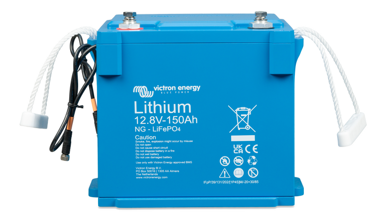
A lithium battery requires a stable charging voltage. For LiFePO4 batteries, the correct charging voltage is usually between 14.2 and 14.6 volts, depending on the make and BMS type. A standard dynamo with a built-in voltage regulator isn’t designed to stay within those tight margins. This can result in the lithium battery never reaching a full charge.
It may also be that the voltage rises too much at higher RPMs. If the voltage is too high, the BMS intervenes and interrupts the charging current. This can cause sudden voltage spikes in the vehicle’s electrical system and lead to damage to sensitive equipment or the starter battery. The correct charging profile and a specific voltage are therefore very important.
Dynamo or wiring overload
A lithium battery will keep drawing maximum current. This causes a standard dynamo to overload. Components such as the internal wiring, fuses, and connections aren’t designed for this. Eventually, the V-belt could even burn out.
Especially with boats that have older engines or motorhomes with thin cables running between the engine bay and the battery bank, this is a problem. Therefore, it’s important to have everything in order for the lifespan of your battery and other systems.
Two clever solutions: external charge controller or DC-DC battery charger
Ensuring the dynamo remains protected against overload and overheating can be achieved in two ways: with an external charge controller or with a DC-DC battery charger. We’ll happily explain more about these options for safely and responsibly charging your lithium battery.
Lithium batteries have a low internal resistance, allowing them to draw high currents when charging, especially in more modern vehicles with so-called ‘smart dynamos’. These are controlled by the onboard computer and don’t supply power constantly, meaning charging lithium batteries requires extra care. Therefore, it’s important to choose a suitable battery charger that performs well in different ambient temperatures and prevents the battery from being charged if it’s too cold or too hot.
Charging a lithium battery with an external charge controller
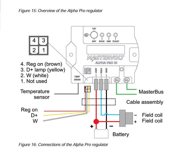
An external charge controller’s role is to replace or control the dynamo’s built-in voltage regulator. The system allows the dynamor to operate at full power, monitors voltage and temperature, and automatically adjusts the charging profile to suit the battery type. It adapts automatically to the conditions.
With an external charge controller like the Mastervolt Alpha Pro, the full output of the dynamo remains available and there’s no risk of overloading. It’s a sound solution, particularly for larger boats or systems with high energy demands.
Charging a lithium battery with a DC-DC charger
A DC-DC battery charger works a little differently. This charger is connected between the starter battery and the lithium battery. This way, the dynamo first charges the starter battery, after which the DC-DC charger controlledly passes current to the lithium battery. The charger determines how much current it allows through and keeps the charging voltage within safe limits. You can also set it with a maximum charging current to prevent overloading.
You can use multiple DC-DC battery chargers in parallel to get more power. This makes them ideal when working with multiple battery banks. They’re also a good choice if you have space and cabling limitations.
Which option suits your situation best?
Every installation is a bit different. When making the right choice when switching from a lead-acid battery to a lithium battery, it’s wise to take into account your current engine, dynamo, battery bank, and usage needs.
Choosing an external charge controller
We recommend opting for an external charge controller if you want to get the most out of your existing dynamo. This solution is particularly well-suited to larger boats with a high energy demand from a substantial battery bank.
Even if you sail for a long time and often, an external charge controller has a clear advantage. Because the dynamo can deliver its full power, it can simultaneously supply power to the battery and other systems without overload.
Choosing a DC-DC battery charger
If you’re after flexibility, for example if you’re working with multiple battery banks or different battery types, then we’d recommend a DC-DC battery charger. The charger can be set to regulate the charging current and voltage itself. This protects both the dynamo and the battery from varying engine speeds.
You’ll also need a DC-DC charger if you plan to add extra battery banks or expand the system later. This is because multiple chargers can be placed in parallel to increase charging capacity. For the DIY enthusiasts among us, this is therefore a sensible and flexible choice. You can also combine and expand different power sources with it. Overloading the dynamo is almost impossible with this setup.

Charging via a smart dynamo from AB Marine Service
Connecting a lithium battery directly to a standard dynamo, that’s not a good idea. Opt for an external charge controller or a DC-DC battery charger to safely and responsibly charge your lithium battery with a dynamo.
Do you have any questions about your situation? Don’t hesitate to get in touch with us. We’ll be happy to help you make the right choice. That way, you can soon be back on the water without a care, thanks to a modern battery system.