More and more Dutch people are enjoying the convenience of electric boating. Do you also want to make your boat electric? You can! With modern propulsion systems, powerful battery packs, and smart solutions from AB Marine Service, you can convert your own boat and sail whisper-quiet from now on.
We’ll explain everything about the advantages of electric boating and the clever Python-Drive system. We’ll also provide a step-by-step plan for electrifying your boat and give you an idea of the costs involved. We’re happy to help you make the best choices.
Inhoudsopgave
Why you should electrify your boat
Anyone who has ever sailed an electric boat knows it’s a world apart from traditional diesel or petrol-powered systems. Electric boating is more comfortable, reliable, and cleaner. We’ve listed some of the advantages.
More environmentally friendly: sustainable boating without emissions
Anyone who has sailed an electric boat doesn’t have to contend with exhaust fumes, fuel smells, or harmful emissions on the water. Whether you have a tender, a motorboat, or a sailboat: electric boating is simply better for the environment.
Reduced costs: less maintenance required
With a traditional engine, you have to change oil, clean filters, check impellers, and so on. With an electric motor, you have far fewer moving parts. This means less wear and tear. This saves you money, time, and hassle every year.
Quieter boating: less drone and vibration
A petrol engine creates noise. You’ll enjoy nature much more if you can actually hear it while you’re out and about. It’s also pleasant to hear more of your surroundings in busy marinas or urban waterways. With an electric outboard motor, you’ll cruise along whisper-quiet.
Less polishing: your boat stays cleaner
A petrol or diesel engine always brings dirt with it. The smell of fuel seeps into your boat and before you know it, you’ll have oil, grease, or other stains somewhere. With an electric motor, everything stays fresh and clean. This is another way in which electric boating provides more comfort.
More control: easier manoeuvring
Another advantage of electric boating is that it makes the experience more enjoyable. An electric drive is more direct, precise, and smoother. When you accelerate or steer, you notice this immediately. This helps with manoeuvring in narrow canals or when docking.
More value: another plus of electric conversion
In an increasing number of cities, harbours and nature reserves, stricter emission rules are being introduced. By converting your boat to an electric vessel, you won’t encounter any problems with these. Furthermore, it increases your boat’s value. That’s beneficial if you want to sell it later on.
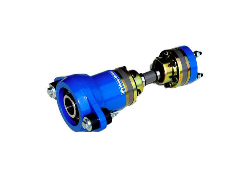
How the Python Drive + hub makes conversion easier
The Python-Drive is a revolutionary component for electrifying your boat. This system connects the electric motor to the propeller shaft. With a matching hub, you can connect the motor directly to the Python-Drive, without any intermediate pieces or welding.
No separate parts or welding needed
Thanks to the clever solution of a Python Drive and a hub, no extra couplings, welded joints, or mechanical adjustments are required. All components are precisely matched for your boat.
Advantages of a compact design
A Python Drive takes up little space. This is ideal for boats with limited engine compartments. It therefore also makes installing an electric Drive easier. Furthermore, it makes your engine compartment tidier.
Clamping force and alignment are well managed
The hub provides ideal clamping force between the engine and the drivetrain. The constant velocity joints effortlessly compensate for minor misalignments. This is one of the reasons why the Python-Drive is so popular worldwide for recreational boats.
It works better than a traditional reversing gearbox
With an electric system, you no longer need a gearbox. The Python-Drive completely replaces the gearbox. This also means significantly less wear and tear. It makes your boat reliable and virtually maintenance-free.
Less vibration in electric motorsn
The constant velocity joint absorbs axial and radial movements. This ensures you can cruise without vibration, even at high power. An electric boat with a Python-Drive therefore sails silently, both audibly and in terms of movement. This applies to larger sloops too.
Simple installation for every type of boat
With the Python-Drive, you can convert virtually any motorboat, sailboat, or sloop. The system is flexibly mountable and therefore ideal for the handy DIY enthusiast. This makes converting to an electric boat easier than ever for many boat owners.
Converting your boat to electric power, step by step
Many people think converting their boat to an electric system is complicated. Fortunately, it no longer needs to be. We offer complete kits with everything you need: from the motor frame to the wiring loom and from the lithium battery to the battery charger.
Step 1: Remove the old diesel engine
You obviously start by removing the old diesel or petrol engine. Disconnect all fuel hoses, tanks and exhaust systems. Then you’ll have all the space to clean this part of your boat thoroughly and get started with the electric system.
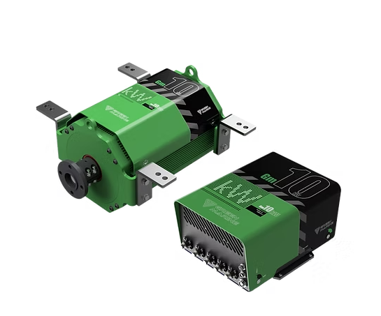
Step 2: Install the electric motor and hub
You mount the electric motor on the supplied motor frame. Then, using the supplied hub, you neatly connect everything: the propeller shaft, the motor and the Python-Drive. This keeps everything compact and tidy in your electric boat.
Step 3: Connect the cables
Now it’s time to connect the cables between the motor, controller, battery, and throttle. You’ll do this using the supplied cable set. Follow the instructions carefully when connecting everything. This ensures everything works safely and efficiently.
Step 4: Charge the battery via shore power
Using the supplied lithium battery and its charger, you can charge the system via shore power. Once the battery is full, your boat will be ready for its maiden voyage powered by electricity, without any engine noise, smoke, or vibrations. That’s what you call carefree boating.
What does it cost to convert your boat to electric propulsion?
The cost of electric boating depends on various factors. These include the desired power output, the desired cruising time, the required battery capacity, the weight of the boat, and the length of the boat.
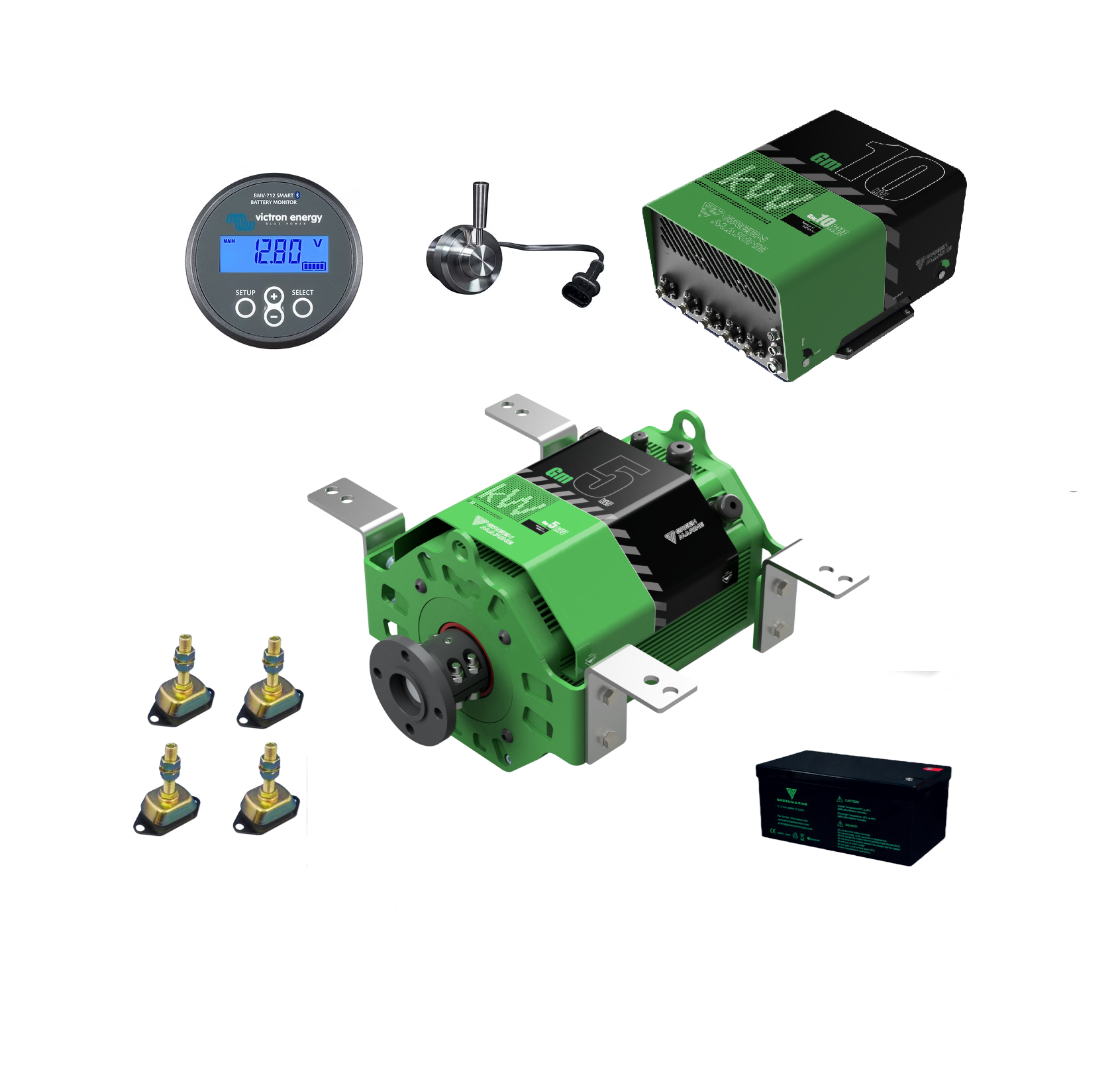
At AB Marine Service, we offer three complete kits from Green Marine to electrify your vessel yourself. We’ve listed them for you:
- Kit 1: 10 kW – up to 5 tonnes – replaces 30 hp
- Kit 2: 7.5 kW – up to 3 tonnes – replaces 25 hp
- Kit 3: 5 kW – up to 1.5 tonnes – replaces 15 hp
The kits contain everything you need to convert your boat to electric. The system for small boats costs around €10,000. The system for large boats costs around €20,000. For a medium-sized boat, you’re looking at approximately €15,000.
This investment makes boating more comfortable, smoother, and better for the environment. What’s more, you’ll save on fuel and maintenance, and it will increase your boat’s value. Most boat owners never want to go back after discovering electric boating.
Converting a boat to electric with AB Marine Service
Fancy electrifying your boat? Feel free to get in touch. We’re happy to provide expert answers to help you make the right choices. Our specialists will gladly advise you on which Python-Drive model or electric motor hub best suits your setup, and you can also use our calculator to find the correct model.