Here are some tips in the event that you have a battery-related problem or a malfunction in the starting system.
If the engine of your boat has little or no power to start, the starter motor or battery may be defective.First things first: make sure that you have checked the following before you start looking at replacing these parts. Several other things, such as a corroded main fuse, mass switch or soiled electrical connections and poorly connected wiring, may be the cause of a starting problem.
Make sure you are safe before you start working.The engine should only run through the starter motor without starting, so turn off the fuel supply. This can easily be done by using the stop solenoid or by putting the throttle in the stop position. Let’s get the multimeter out and do some testing!
1. Battery check in a few steps!
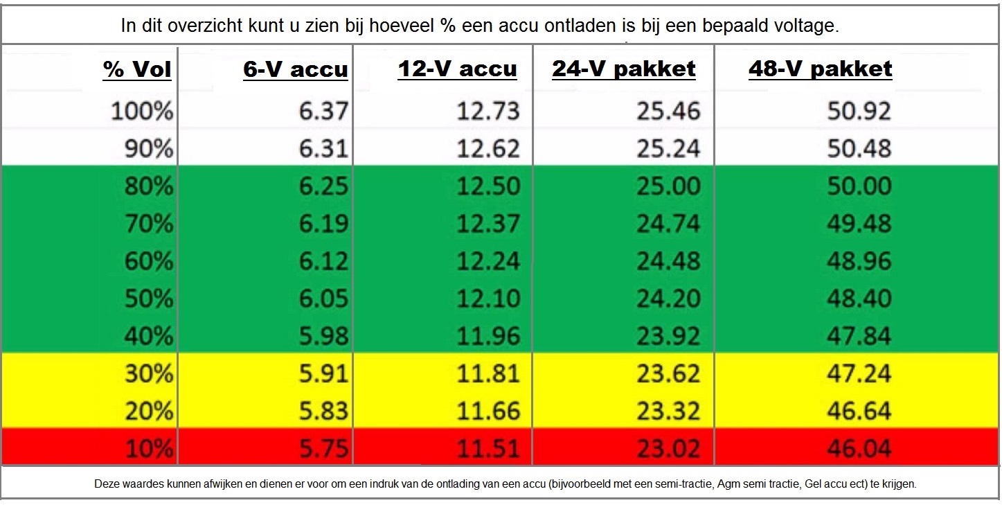
Step 1: A full battery; set the multimeter to DC (direct current) voltage, connect the red probe to the positive and then the black probe to the negative battery terminal. If the multimeter indicates that the battery output is less than 12 volts, first charge or replace the battery before we continue. At 12.4 volts, the battery is fully charged. Double that figure (24.8 volts) for a 24-volt battery. A few millivolts more or less is okay.
Step 2: Put the multimeter back on Direct Current. Connect the red wire of the multimeter to the positive terminal of the battery, and then the black wire to the negative terminal. Proceed with step 3.
Step 3: Turn the ignition lock to the “Start” position and start the engine, keep it going for about 4 to 5 seconds.Read the voltage as shown on the battery multimeter while starting the engine.The battery is in order if the multimeter reading exceeds 9.5 volts during start-up. A reading of less than 9.5 volts indicates too high a drop in voltage. The cause may lie in a poor chemistry transfer in the battery itself due to age. About time to replace it! Battery in order? Keep on reading.
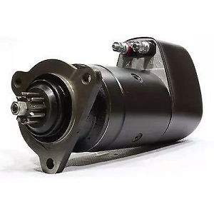
2. Weak starter.
Since the battery has found to be in order or replaced, it is now time to have a look at the starter motor. Even though the battery was the only problem, the following test may prevent many headaches in the future. Corrosion is a common problem. Check the connections from the battery to the starter itself for any deposits, including the negative terminal. Also check the condition of the connection between the starter and the engine block. This includes disassembly and inspection, but taking measurements could be a faster option in this case. This can be done as follows:
Step 1: Put the multimeter on Direct Current. Connect the red probe to the positive battery terminal and then on the relay connection of the starter, from where the copper cable enters the starter motor. This is the last connection before the + plus disappears in the starter motor itself. Below called the “M terminal”.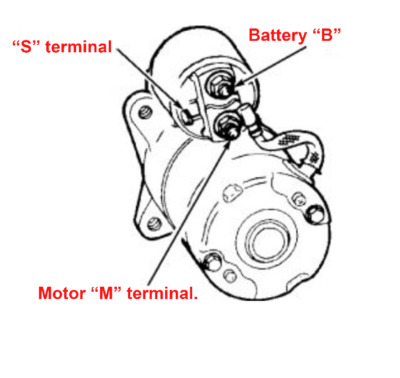
Step 2: Turn the ignition lock to the “Start” position and start the engine without running it. Read the voltage as shown on the multimeter while starting.
Step 3: Without drop in voltage between the cable and the starter relay, you should now read 0 volt. But people often read 0.1 volt, and 0.1 to 0.2 volt is no exception for older systems.
It means a voltage of e.g. 12.1 volts starts from the battery, but – due to resistance or a poor contact – ends up at only 12.0 volts. A multimeter measures the voltage difference.So the multimeter will measure a “difference” of 0.1 volt, any number higher than 0 volt indicates resistance. This process can be repeated on the plus terminal for each individual contact and connection, as well as for the negative terminal. That is because every positive electrically charged atom that goes in has to come out again via the negative terminal.
Step 4: Add up the values of the measurements in the previous steps. The sum of these values should not exceed 0 to 0.3 volt. The lower the number, the better it is. Just think of it. When starting an ordinary 4-cylinder boat engine, it will run up to 1000 Amps for a short period of time from standstill, after which it will drop until the engine runs at about 200 to 300 Amps. Until the engine runs 1000 Amps with 0.3 drop in voltage, the starter motor will drop 300 Watts. For a standard nominal 1200-Watt starter motor, it means that 25% of the starter capacity is lost. It shows that a minor drop may have major consequences. (example)
3. Conlusion.
First fix the resistance loss and then check that the power of your starter motor is back.
This was about testing the power supply of your starter system. If the starter motor still fails to give full power, it may have an internal defect. In that case, we suggest that you contact one of our specialists for more information about a possible solution.
Facts!
R = U / I or Resistance = Voltage / Current or Ohm = Volt / Ampere (Ohm’s law)
P = I * U or Power = Current * Voltage or Watt = Ampere * Volt
Watt = Ampere22 * Ohm
Watt = Volt / Ohm
Ampere = Watt / Volt
Volt = Watt / Ampere
An example with water flowing through a tube gives a better insight into the difference between current and voltage:
Electric charge in volts:pressure of the water in a tube.
Current intensity in Amperes:amount of water per second flowing through a tube.
Resistance in Ohm: thickness of the water tube.
Power in Watt:force of the water against e.g. a paddle wheel.
Click here to read more about replacing the starter motor

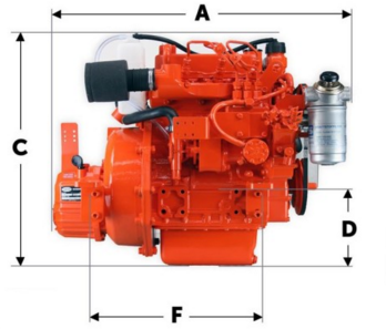

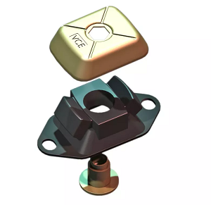
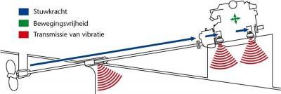
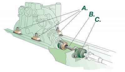 So what is the optimal engine mount?

 A fuel tank is often installed inside. In the evening, the tank cools down and warms up again during the day. The oxygen that moves through the warming and cooling process always contains moisture. Warm air that cools down forms water droplets (rain), and this condenses against the walls of the tank. This water drips down and settles at the bottom of the tank, below the diesel. Diesel has a lower specific gravity than water. A practical tip is to keep the space above the fuel as limited as possible. Always fill the tank completely before leaving the boat unused for a long time (for winter storage with winter diesel). After all, the less space there is at the top of the tank where oxygen and condensation can settle on the walls of the tank, the better. Warm and moist conditions are also perfect for diesel bacteria to grow rapidly, but even during winter, diesel bacteria can thrive. A clean and dry tank vent in the right place is therefore recommended. Rain and wave action Even incorrect placement of, for example, the fuel fill or vent can quickly cause water accumulation in the tank. Rainwater that can seep in through an external vent, or splashes of waves hitting the deck, can get into your tank, so this needs to be taken into account. Also, pay attention to a proper seal of the diesel fill cap on the outside and periodically check the seals in the cap. Is this new? Diesel today must contain less sulfur than in the past, as required by the government. Sulfur that you burn is highly polluting for the environment, but sulfur used to prevent bacterial growth in the past. In addition, a few percent of biodiesel is now added to diesel. Biodiesel is made from plant-based products and is therefore interesting as the world’s oil reserves are depleting. But biodiesel has the property of quickly attracting water and contains a higher percentage of microbes. What can you do?
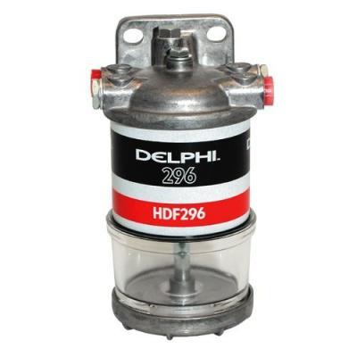
  If possible, check visually if you can see water formation in the tank, often you’ll see a large “bubble” of water at the bottom. If you have never checked or drained it, that’s a good start. Do you frequently encounter this problem? Look at what the cause might be, as described above, such as malfunctioning venting, etc. The fuel supply pump that delivers fuel to the engine also often pumps the diesel back into the tank several times through the return line. This way, your tank is often kept clean and filtered. A proper filter installation with a water separator can catch water from your tank. Since water is heavier than diesel, it is collected at the bottom of the glass. Through the glass, you can also see whether your diesel is clean or maybe cloudy, which indicates contamination. Do you experience a lot of contamination and have trouble draining the tank? Then you can opt for an external pumping system that continuously circulates the diesel through a filter set and separates the water.