Every boat needs a bit of regular TLC, and that goes for the engine too. Without attention, dirt and build-up can lead to poor combustion, loss of power, and in the long run, damage.
A periodic clean is certainly a good idea, especially when using biofuel. Biofuel can contain more bacteria than conventional fuel, although this isn’t an inherent characteristic of all biofuels. The increase in bacteria in biofuel, particularly biodiesel, is mainly due to its higher organic content and the presence of water. This creates favourable conditions for micro-organisms to thrive. This can lead to bacterial growth in the fuel tank and blockages in the fuel system.
Time to give your diesel engine a thorough clean. In this guide, we’ll explain step-by-step how to treat your engine to a good spruce-up. This way, you’ll avoid costly repairs down the line and can set sail with peace of mind.
Why cleaning a diesel engine is important
Diesel engine pollution often builds up very gradually. You usually only notice it when the power drops a bit or fuel consumption increases slightly. We’re listing five benefits of a clean diesel engine.
Reduction of wear and tear
The more dirt, soot or fuel residue in your fuel system, the more friction and pressure you’ll get. Parts like injectors, the fuel pump and valves will struggle bit by bit. If everything is clean, your engine will last longer.
Improving combustion
The cleaner the engine, the better the diesel combustion. You can tell this by a powerful and regular engine sound, both when idling and when cruising. Usually, it also sails a bit smoother. An experienced skipper notices this almost immediately.
Cutting emissions
If there’s dirt in the engine, you’ll also suffer more from exhaust fumes. This includes fine dust, harmful exhaust gases, and other noxious substances. Therefore, a clean fuel system is better for your boat, the environment, and your own health.
Step-by-step guide: how to tackle cleaning effectively
Fortunately, cleaning your diesel engine isn’t too tricky a job. With a handy step-by-step guide and the right tools, you’ll get a long way. We’ll explain how to clean your diesel engine in a few simple steps.
Step 1: A visual inspection
It starts with a thorough check. See if you notice any oil or diesel residue, if the air intake is clear, and if there’s any soot buildup. The oil level and colour are also worth inspecting. Have you checked the basics? Then it’s time for a proper clean.
Step 2: Use Diesel Cleaner
with Diesel Cleaner. This fluid cleans the Diesel Cleaner. This fluid cleans the entire fuel system. Pour the contents into the fuel tank before refuelling. It improves combustion, optimises fuel consumption, and resolves carbon and soot deposits.
Step 3: Use Injector Cleaner
For an even cleaner engine, we also recommend Injector Cleaner. This fluid cleans the entire fuel system. Pour the contents into the fuel tank before refuelling. It improves combustion, optimises fuel consumption, and resolves carbon and soot deposits.
AB Marine Service’s Recommended Products
We therefore recommend Diesel Cleaner and Injector Cleaner. And while you’re at it, it’s also a good idea to use Radiator Flush to clean your cooling system. This agent cleans blocked coolant passages. You pour it into the radiator and let the engine run for 10 minutes.
Next, it’s time to replace your coolant. Our recommendation is Coolant -38 NF from Kroon Oil. This coolant can be used all year round and offers protection down to -38 °C. The maximum change interval is three years.
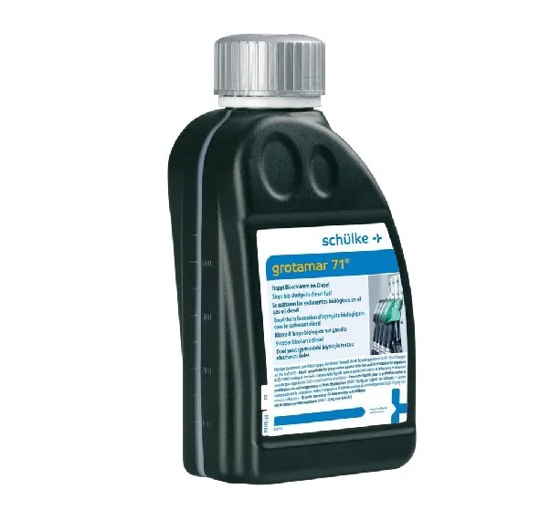
Another recommendation is a bactericidal diesel additive. It prevents the formation of bio-slime, rust and blockages in the fuel tank and lines. Just 25 ml per fill-up protects against water-borne micro-organisms such as bacteria and fungi. Ideal in warm, humid conditions or during longer diesel storage.
Common mistakes when cleaning a diesel engine.
We often see the same mistakes being made during cleaning. To avoid these mistakes, we’ve listed them out. That way, you’ll know straight away what not to do.
Don’t leave cleaning too long
The first mistake is quite logical: waiting too long. If you wait until your engine starts sputtering, you’re already too late. You don’t want internal damage to occur that can’t be fixed with cleaning. Therefore, opt for regular maintenance to have minor contamination cleaned.
Using the wrong products
Not every additive is suitable for your engine. That’s why we only recommend thoroughly tested products from A-brands. For instance, incorrect additives can cause damage to your rubbers or seals. Ultimately, you’ll be worse off.
Using not enough/too much
If you use too much or too little of your cleaning product, it’s possible your results won’t be as you’d hoped. So, always follow the recommended dosage on the bottle. More isn’t always better. Therefore, don’t just chuck in a litre of Diesel Cleaner without a second thought.
Fancy getting your diesel engine cleaned? We’re here to help.
Cleaning your diesel engine isn’t overly complicated. With the right products from AB Marine Service, you’re choosing a reliable approach to keep your engine in tip-top condition. This way, you’ll prevent damage, reduce fuel consumption, and sail with peace of mind.
Got any questions about our products or your diesel engine? Don’t hesitate to get in touch,, and we’ll put our heads together with you. We’re happy to offer you more tips and expert advice.